The VW power plant, what put the "V" in Youngster "V"!
Email me
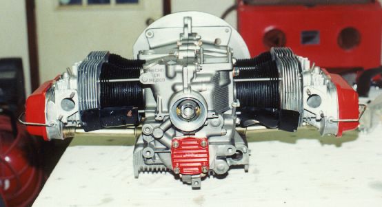
This is a picture Marty Hammersmith's Engine that I really hope he doesn't mind me using.
Real pretty work. Visit his site by clicking here or on the picture above.
Initially I had planned a full keep it simple
and light set up. Single port, 1700 cc, distributor ignition, and
a Zenith up draft supplied from gravity feed. I had several
parts from my sonerai project left over that could be used for on the youngster,
but very few were actually used. Not needing a race plane, just a
dependable one, the parts I had on hand worked just fine.
I splurged and got the full Force One Prop hub up front from
Great
Plains Aircraft Supply to give me that warm fuzzy about the weakness
of the prop bearing problems. I thus wont, have to constantly think
about loading up the prop when being a stick jockey. I'll kept my
compression ratios low to allow the use of Auto fuel. If there
is one thing I've learned from my other building experiences is, keep it
simple and light!
| 8/2/2000 | Today I picked up a set of Single port heads at a major bug shop up the road that seem to be in very good shape, and recently rebuilt. | 1 |
8/3/2000
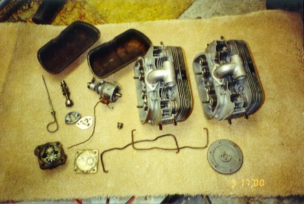 |
Went to a friends house that has been rebuilding a few old bugs, and again gleaned a few parts from him that will serve well in my plans for this airplane. Parts obtained were the valve covers, a new oil pump, distributor, oil pan-filter cover plate. | 1 |
2/28/2001
 |
Ordered the remaining engine parts today.
Won't be long before I can hang it and start rigging the exhaust and intake!
|
0 |
| 3/30/2001 | Engine has arrived! | 0 |
4/7/2001
 |
Finally I got around to moving the engine from my office in the house to the garage where assembly will begin. I took the time to check the inventory, and study the workings of the Force One prop hub system. With a Vixen file, I cleaned up a bunch of the sharp edges on the case. I only need to send off the heads to get them bored to fit the 92 mm cylinders, and the pistons and crank to get them balanced. Heavily varnished engine mount board was drilled to fit the case, great care was given to make the block level to the airframe. | 1 |
| 4/10/2001 | Hauled the crank and pistons down to be balanced today. Should get them back in a couple of weeks. Hopefully sooner. Kind of limited as to what I can get done with out them in house. Sand blasted the valve covers and painted them in the Green trim color, may add some gold pinstripe later. Yep, just kind of looking for things to do. | 1 |
| 4/20/2001 | Picked up the crank and cylinder heads at the shop today. I thoroughly cleaned the Engine case, and painted it as per Great Plains instructions. (oil based enamel 50/50 with gasoline) We'll see how it holds up. Cylinders were washed in the dishwasher under the pots and pans cycle. After dry, I painted black, and oiled the inside. Some time was spent trying to hand lap the Force one hub to the crank. Will mount it in a lathe soon. An attempt was also made at getting a CC reading on the heads. I think I'll try again to reproduce the readings to get a judgment of accuracy. | 3 |
| 4/21/2001 | Spent about 2 hours spinning my prop hub in a lathe lapping the crank. I had to cut a bit out of the back of the hub as the lapping moved the hub too close to the timing gears. | 2 |
| 4/23/2001 | First thing today, I mounted the timing gears on the crank with out problem. Used the oven to heat the gears to 400 degrees and they fell right in place. The rods, and bearings were then inspected and mounted in place. End play of the crank will have to wait till I get an end piece. End play of the cam was also verified. Very close at this point to closing the case. | 2 |
| 4/24/2001 | Still waiting on parts! Did the final checks internal to the case, so that once the crank end play is set, I can quickly close up the case. Final work on cc'ing the heads was completed. Cylinders were lapped into the heads and set aside. All 8 mm cylinder head studs were placed in the case halves. | 1 |
4/29/2001
 |
Having all the parts together, I've finally got around to setting the end play on the crank, and verifying everything internal on the engine case. I guess you could now say that the case is closed!? After setting proper torque on all bolts, crankshaft motion was still quite free. So far so good. Engine was then mounted to the motor board, and 4 spacers created to stand the board off the fire wall about 1/4 inch. Tomorrow, I'll probably hang the engine on the firewall, and do the deck height measurements to attempt to produce a 6.7:1 compression ratio. | 2 |
5/1/2001
 |
Today deck heights were verified, and calculations made to determine needed shims to produce the desired compression ratio. Engine was removed from the motor board to carve out the area behind the back right cylinder to prevent contact with the board. Received the prop today from Ed Sterba. Heads were set on cylinders just for my entertainment. | 2 |
| 5/4/2001 | Well the last few days have been spent waiting for parts, and ideas. Parts are sometimes easier to find than ideas. Yesterday I spent and hour standing in a metal scrap yard picking out some stainless hand rails that I've now cut up into intake parts. The final engine mount bolt was drilled at the top center of the motor board. Having received the 90 degree distributor cap, I had to rotate the distributor drive gear 180 degrees so the wires would exit aft. The Zenith carb was received today and inspected. Throttle spring was removed as was the throttle cable attach device. At present I'm considering mounting the carb facing aft, but too early to know anything. | 3 |
| 5/5/2001 | Even on my 11th wedding anniversary, I got a little done! Got the shims in today, and verified the deck volume and compression ratio of the left bank of cylinders. Both left cylinders, (1,2) were then finally installed and heads torqued in place. | 1 |
| 5/6/2001 | Right cylinder bank was fully installed today. Pushrod measuring tool was used, after modification to fit the rocker arm cup properly, to measure needed pushrod length. | 2 |
5/7/2001
 |
Today I made a trip to "Earl Mann's bug shop" in Ardmore OK. You can search and find him on the internet. From there I brought home 4 "J" tubes, and a few Single port intake manifold parts. These ought to speed things up mightily. I in fact will be setting aside the Monnett single port manifold parts that I originally acquired the single port heads for. Best laid plans? Also picking up several nuts and bolt, I've got plenty to keep me busy for tomorrow. Only work done on the actual engine was to install, torque and pin the force one prop bolt. | 1 |
5/8/2001
 |
Made the run to the muffler shop and got some good help there. As feared, We were unable to bend the pipes as close to the mount flanges as I wished, so some radial cuts and welds will be required to fit the pieces together. A single piece of tubing was fitted between the stock single port manifold pieces mounted at the heads. Another piece was cut and prepared to receive the carb mounting flange. Tomorrow will bring more cutting, grinding and welding. | 2 |
5/14/2001
 |
The intake manifold system is complete.
Finished welding today, and will only need to paint it, and support it
somehow. A side note here about the use of the stock manifold head
pieces. They rise up fairly high, and will allow a nice sized eyebrow
baffle.
The right intake header is about 80% welded up, and looking quite. . . .acceptable. Pretty simple cheap, and should allow adequate locations for carburetor heat boxes. Someday, if I'm having fun, maybe even a cabin heat muff! . |
3 |
| 5/16/2001 | Moved to the forward end of the carb today. A piece was machined that would mount to the flange of the carb, and then be attached to a piece of 2 1/2" aluminum tube at a 90 degree angle. In this would be mounted a flapper valve, to allow either fresh or heated air. Those "fly-market" fans would appreciate that I used that miracle "alumiloy" welding rod to attach the machined flange to the 2 1/2" tubing. I now need a step down to allow the heat end of the tube, to be run down to the heat muff below the engine. | 3 |
| 5/19/2001 | Back to the basic engine assembly today. I adjusted the distributor installation to assure clearance from the distributor cap and the carb heat box. The fuel pump pushrod was sized and installed. Fuel pump was also installed. An attempt to install the oil pump was made, but the drive gear requires adjusting. All intake parts were removed to be painted. The carb heat box was trimmed on the heat intake end, and a flapper valve was cut to shape. I installed a small copper loop to serve more as a oil cooler bypass, but with 24" of 3/8" copper tubing, it may have a bit of cooling properties. | 2 |
| 5/20/2001 | Adjusted and assembled all parts to the carb heat box. A 2" hose will run from here to the lower engine to obtain the hot air from a muff on the exhaust pipe. All intake parts were then primed and painted. Hope I'll get them all installed tomorrow. The oil pump drive gear was adjusted and installed along with the rest of the oil pump. | 2 |
5/21/2001
 |
Installed the entire intake system today as planned. All went well. Need to build a brace for the carb heat box to support that end. A bit of time was spent shaping the "stock" cowling provided with the kit. I think I'll be able to make it work, but it's going to take some glass work. The left bank exhaust header was cut shaped and welded in a mere fraction of the time I produced the right bank. I wish I could do the right bank again with what I know now. The Gascolator was mounted and the internal plumbing was hooked up in final configuration. Carb to fuel pump hose was put in place. | 5 |
5/22/2001
 |
Today's time was spent solely on welding and cutting the exhaust system. From the cylinders to the tail pipe that leaves the cowl is finished and awaiting paint at this point. I'm a bit tired to looking at the end of a welding torch. | 2 |
5/23/2001
 |
Finished the sandblasting today. The pipes were then painted with cermachrome paint and baked. The pipes were then positioned on the engine so pictures could be taken. I also took a few minutes to fashion a support for the carb heat box. Tomorrow will start the final wiring, and hooking up engine controls in preparation for it's first run. | 2 |
| 5/24/2001 | After errands, not much time to do the work on the project. I did, however, get the carb heat, and choke cable hooked up and operating. A throttle arm was fashioned and attached to the carb, as well as a temporary cable attachment. A simple quadrant will need to be created next. The remains of the day were spent cleaning around the airplane in preparation for the weight and balance. | 2 |
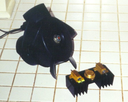
| 5/25/2001 | Met with another prospective builder today from the DFW region. David H. came by this morning at 0900 and we had a good talk about the airplane and its 'virtues' After his departure, I was able to construct a simple Throttle quadrant, and a couple of "bug nut" cable attachments for each end of the throttle cable. Works very smooth, and solid. After this my attention was turned to the final wiring of the engine compartment. The coil was wired, from master ignition switch to the points lead at the distributor. The coil itself was hung on the firewall just above the engine mount on the right side. When time ran out I was working on a common ground terminal for the entire aircraft. | 3 |
5/26/2001
 |
Oil pressure relief pistons and springs were the first order of the day. The rear piston took some light adjustment to fit properly. Making the wiring look intentional, and neat, was the remainder of the mornings goal. All wiring was enclosed in a single central spiral wound harness. The plug wires were installed, and the timing set on the 009 distributor. Plug wires were secured into a harness, but will still need to be secured to their respective plugs, and distributor lugs before flight. Exhaust was removed and stainless steel shields were placed where the rear cylinder's exhaust passed in near proximity to the fabric. Exhaust was then repositioned with sealant and nuts placed for final installation. Fuel line from gascolator to fuel pump was placed in firesleave, and attached in place. Gentlemen, we have an engine ready to run! | 5 |
5/29/2001
 |
After a quick check of all attached, and the addition of fuel, oil, and a quart of sweat, I got the engine running! Had to tweak the idle mixture a bit, but it ran and idled smoothly at and below 2000 rpm. Oil pressure is a bit lower than I expected, but it is a used pump, and may ought to go ahead and replace it. | 1 |
| 5/30/2001 | Today I changed out the oil pump a few times to try to advance the oil pressure a bit. Adding a few washers below the oil pressure regulating spring, using the melling oil pump, and the new stamped steel face plate, I've got the oil in the window of where I expect to see it for a new engine. I am though, going to replace the oil pump with a new one to make it the best, not just good enough. CHT, and EGT probes were added today, and wired into the instrument panel. After several runs, I changed the oil. Tomorrow's plan is to create a Carb heat muff. | 4 |
| 5/31/2001 | Carb heat muff is installed. Didn't get a chance to run the engine to determine just how effective it is, but that time will come soon. Only remaining item on the engine itself, is the creation and installation of eyebrow baffles. I started the back bulkhead of the left bank at this point. the biggest effort will be the baffle the covers the cylinders and head. I hope to use the VW plug baffle seals if I can get the holes drilled the right size, and aligned properly. | 3 |
| 6/1/2001 | Today's efforts were strictly spent on the design, and construction of the eyebrow baffles. The left side was completed, and installed. The right side was crafted, and painted. Hopefully it will be installed in the morning. | 4 |
| 6/4/2001 | Attached lower cowl mounts to firewall. Tinnerman anchor nuts were attached to these mounts and lower cowl fitted. Upper cowl was then attached, and marked for the addition of material to better fit the engine. Fiberglass was then mixed and applied to augment gaps in the original cowling. Tomorrow, touch up fiberglass, and ad bondo to prepare for paint. | 2 |
| 6/5/2001 | Trimmed the cowling some more today, and touched up the fiberglass of yesterday. Haven't started with the bondo yet. Too many irons in the fire lately. | 1 |
| 6/6/2001 | Spread the bondo today where needed on both cowlings. Won't be perfect, but my goal is not a show winner, but a light fun aircraft that falls with in the specifications of the designer. All cowling surfaces were sanded in preparation for painting. I also installed a hose to the breather and placed a spring into the hose to prevent collapse at the tight bends. | 2 |
6/7/2001
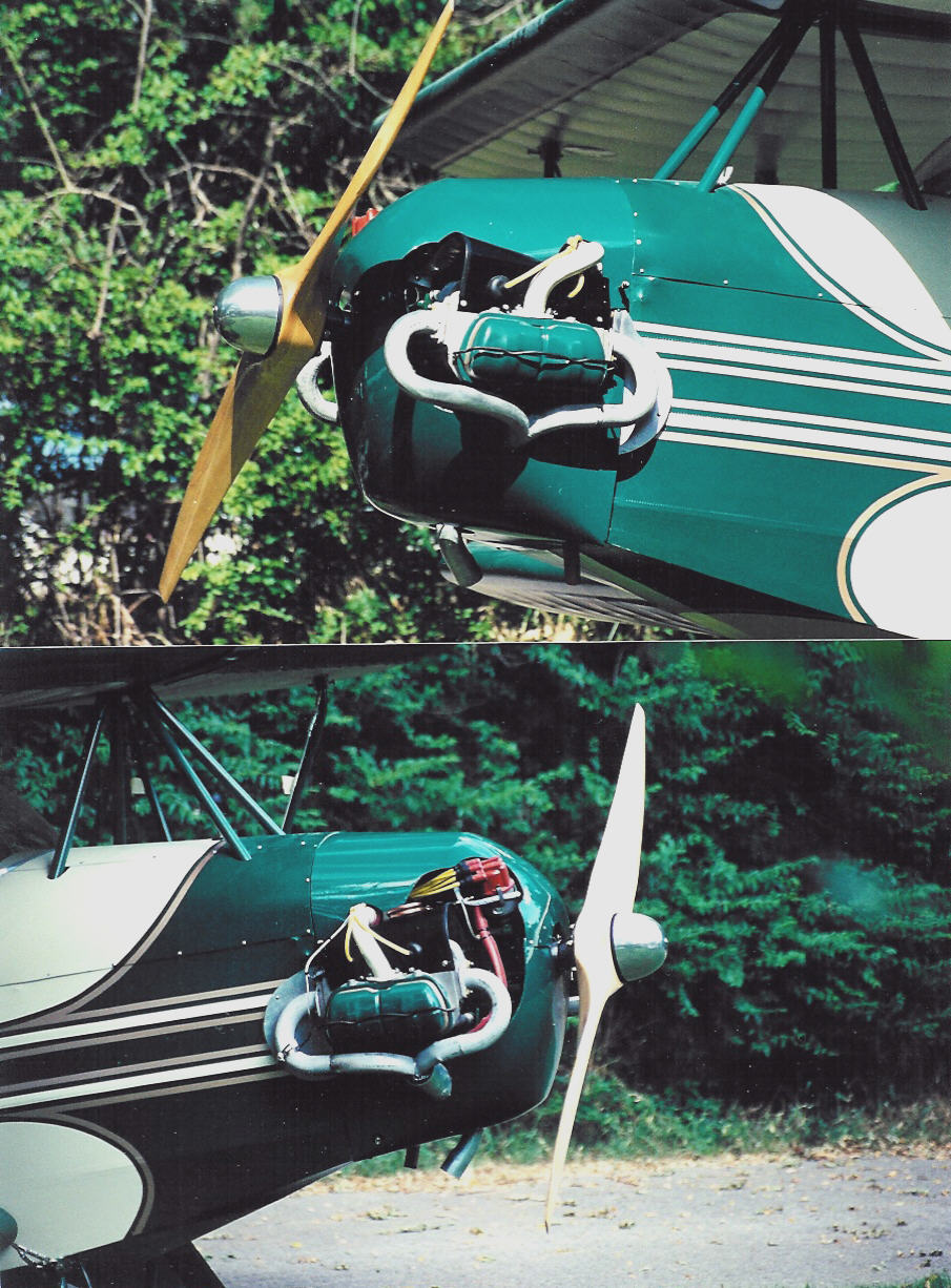 |
Final sanding and cleaning of the cowling and wing connection fairing completed, then shot with paint. Once dried they were attached to the firewall and wings. Though the color isn't quite a perfect match, they'll do. | 2 |
| 6/8/2001 | Removed the cowling today, and installed a set of EMPI high pressure springs, and a new Melling oil pump. I then took the airplane outside for another engine run. All pressures were in the range I am now comfortable with. Good strong and smooth run. Engine run lasted for right at an hour, only momentary stops to check for leaks. Max static rpm with this carb and prop seems to be around 3300 rpm. I, for now, have set the idle to 800 rpm. One minor oil leak was found around the oil pressure capillary at the engine. | 2 |
| 6/16/2001 | Ran the engine for another hour today. The only oil I can detect is a seeping from the acorn nuts on the oil plan cover plate. This was the first run with the cowling on the aircraft. By thirty minutes into the run, Oil temps were in the area of 200 degrees. I know I'll have more air flowing through the cowling in flight that may make this a non problem, but I went ahead and opened a hole in the front of the cowling to let air flow across the bottom of the engine. I also opened the bottom of the cowl where it meats the firewall. Though I could feel warm air exiting from this opening, I may have to install a lip to induce a low pressure area. I fear that in high angle of attach, it may actual take air in, instead of letting it out. Prop bolts were retorqued, and valve gaps were set for the first time after assembly. Nothing abnormal here. | 2 |